Ion 1.0 / Electronics
Electronics
Vision (on/off switch) modes
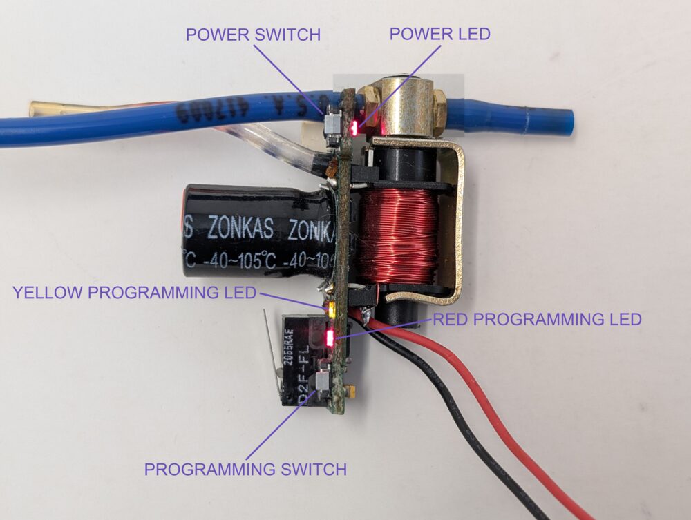
The on/off switch doubles as your safety and mode selector, and its own LED — call it the power LED, to keep it distinct from the programming LED further down this page — shows which mode you're in. Tap the switch to cycle through:
- Vision mode, ready to fire: continuous rapid blinking, four times per second.
- Vision mode, no ball loaded: one blink per second.
- Non-Vision mode (eyes off, marker will still fire): two rapid blinks, then a pause, repeating.
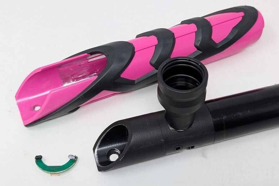
The Ion uses a transmissive (beam-break) eye system — an emitter and receiver on opposite sides of the chamber — housed on a small C-shaped daughterboard that wraps around the bottom of the breech and connects to the mainboard via a 4-pin wire harness. "Vision" is Smart Parts' branded name for what's generically called an anti-chop eye (ACE) system. This is generally reliable; the failure modes worth knowing are paint/debris fouling the eyes, a damaged wire harness, or bent pins in the connector. Removing the board itself is part of the standard Teardown sequence, not a separate procedure — see that page for the actual removal steps.
Programming the board
A small gray button sits directly behind the trigger switch, at the bottom of the circuit board, with a second, two-color LED just above it — call it the programming LED, distinct from the power LED on the on/off switch above. It shows yellow or red, solid or blinking, depending on which setting is selected. With the marker on, press the gray button once to enter programming mode (the yellow programming LED goes solid — setting 1), then continue pressing to step through settings 2–6:
| Setting | Indication | Controls |
|---|---|---|
| 1 | Solid yellow | Dwell — up |
| 2 | Solid red | Dwell — down |
| 3 | Single blink yellow | ROF Delay — up (slower) |
| 4 | Single blink red | ROF Delay — down (faster) |
| 5 | Double blink yellow | Fire mode — cycle up |
| 6 | Double blink red | Fire mode — cycle down |
Yellow always increases the register and red always decreases it — that pattern holds across all three setting pairs, which is why settings 3 and 4 are labeled as ROF Delay (more delay, slower rate) rather than rate of fire directly.
Once you've selected a setting with the gray button, use the on/off button itself to make the adjustment. The power LED stays dark throughout — the confirmation happens entirely on the programming LED. Whichever of its two colors isn't currently indicating the selected setting blinks once per press to confirm it registered: select a red-indicated setting (2, 4, or 6) and the yellow programming LED blinks on each press, stopping once you hit the floor of that setting's range; select a yellow-indicated setting (1, 3, or 5) and the red programming LED blinks instead, stopping at the ceiling. The two LEDs never blink together — only one color, opposite whichever is selected — and the power LED doesn't light at all during programming.
Fire modes cycle in order: semi, rebound, 3-shot burst, full auto.
- Semi: one shot per trigger pull.
- Rebound: fires more than one shot per pull if you pull the trigger at a constant, rapid pace — lets a fast trigger finger get automatic-like output without the marker actually free-running. Comparable to what modern boards call "ramping," though the Ion's version has no configurable ramp ratio — it's an earlier, simpler take on the same idea.
- 3-shot burst: up to three consecutive shots per pull. Release the trigger before all three fire and it stops early.
- Full auto: fires continuously for as long as the trigger stays held back.
UK boards (green power LED, instead of red) skip full auto and 3-shot burst entirely. Semi and rebound are capped at 17 balls per second (BPS); full auto and 3-shot burst cap lower, at 10 BPS.
There's no way to change fire mode without opening the grips to reach the programming button — this doubles as an adequate tournament lock for fields that restrict certain modes.
Dwell & rate-of-fire calculator
Dwell and ROF Delay together determine how fast the board can theoretically cycle. Adjust either one below to see the effect — useful for understanding the tradeoff before you start clicking through settings on the marker itself.
This is the board's electronic timing only — dwell plus ROF Delay, the two settings from Programming the board above. It doesn't account for mechanical limits (bolt cycling speed, air supply flow) or the board's own firmware cap — semi and rebound are capped at 17 BPS, burst and full auto at 10 BPS, regardless of how fast the calculated cycle time would otherwise allow. Useful for understanding why a given dwell/ROFD combination behaves the way it does, not as a guarantee of real-world rate of fire.
On stock values: the Ion 1.0's Version 2 manual publishes both stock figures — 52 dwell, 50 ROF Delay, the exact same pair as the Epiphany's manual — in its CPS table. The base (Version 1) manual only mentions the stock dwell value.
Stock board technical specifications
| Component | Spec |
|---|---|
| Microcontroller | Atmel ATmega48V10MI (AVR), running at 5V off a National Semiconductor LP2981 voltage regulator |
| Solenoid FET signal | Normally high; drops for 4.04 ms, then pulses at 7.813 kHz |
| Solenoid | Manufactured by Humphrey, rated around 4-ohm, wound with roughly 60–70 feet of 32-gauge wire, enamel-coated |
| Trigger microswitch | Omron D2F-FL — a 25-gram lever switch, the lowest return weight available in that series |
| Wire harness connector | Shrouded, top-entry, 4-point JST eSH series |
| Eye wire harness | 28 AWG wire |
| Power capacitor | 2200 µF radial electrolytic, runs straight off battery voltage — required for the solenoid to fire correctly |
| Sealing | Solenoid and electronics are sealed and water-resistant, but not submersible |
Specs via zdspb.com, used with permission — see the disclaimer for attribution terms.
Solenoid service
The solenoid sits right below the firing assembly, releasing air that's plumbed into both the body breech and the fire chamber. It gets fouled by the same grease/debris that affects the bolt — service it at the same interval. Smart Parts' suggested frequency is every few thousand pressurized cycles; running a QEV stretches that interval out, though it still needs occasional attention either way.
| Coil wrap | Solenoid | Safe in an Epiphany? |
|---|---|---|
| Red wrap, black Ion logo | Epiphany-rated (or Epiphany-rated Blackheart) | Yes — this is the one you want |
| Black wrap, red logo | Pre-Epiphany Blackheart | No |
| No wrap | Standard Ion/SP-8 | No |
| Varies | Aftermarket | No |
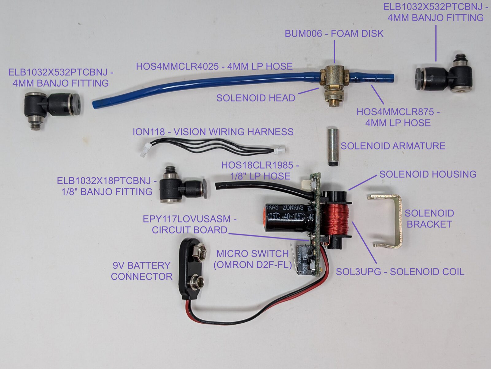
Part numbers from the official Smart Parts Ion Operation and Maintenance Manual. Trigger microswitch identification (Omron D2F-FL) via zdspb.com, used with permission — see the disclaimer for attribution terms.
Two o-rings in that breakdown are hidden inside already-assembled parts — the solenoid head o-ring and the barb/banjo fitting seals. I pulled a few apart to show them directly:
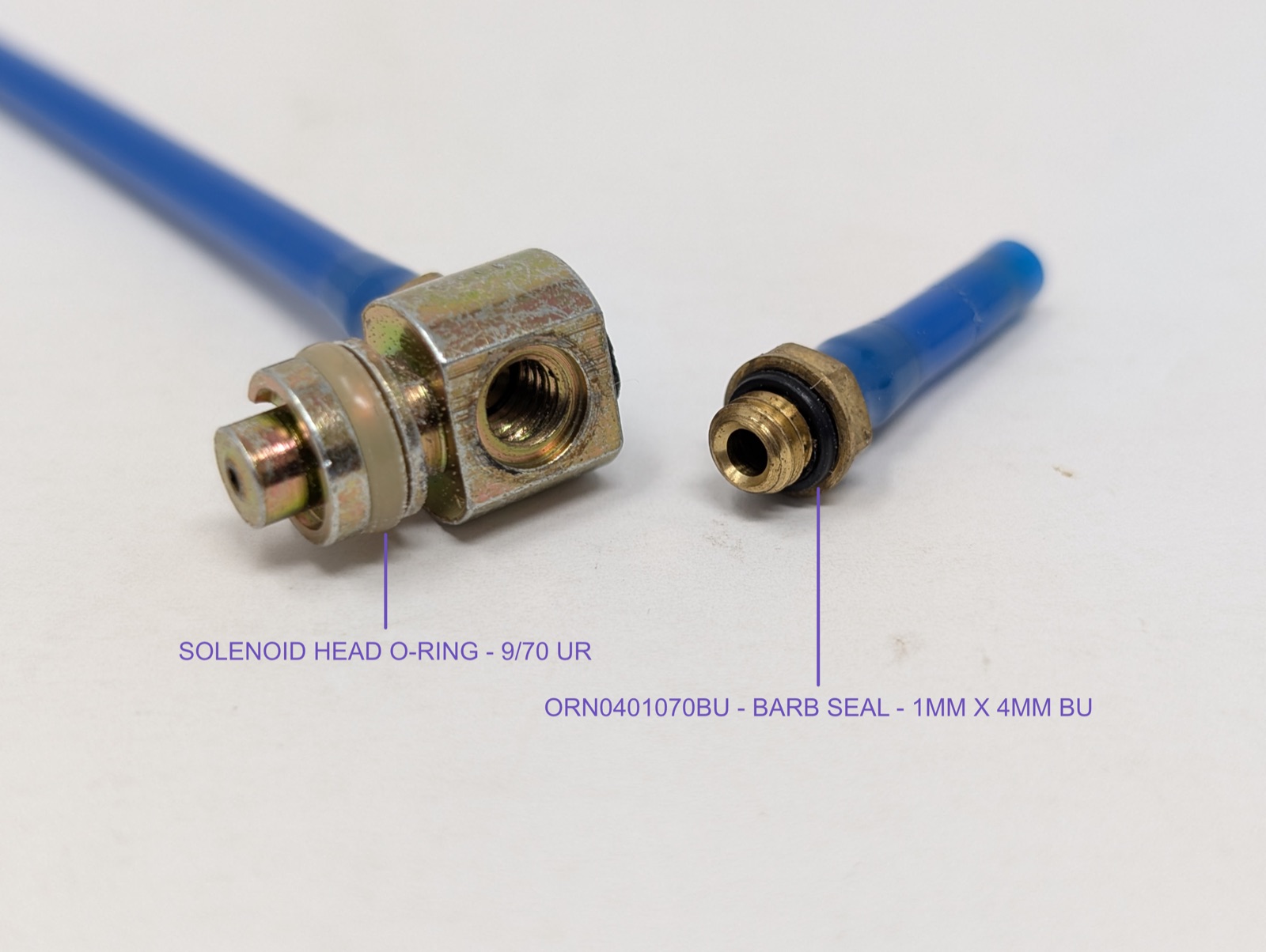
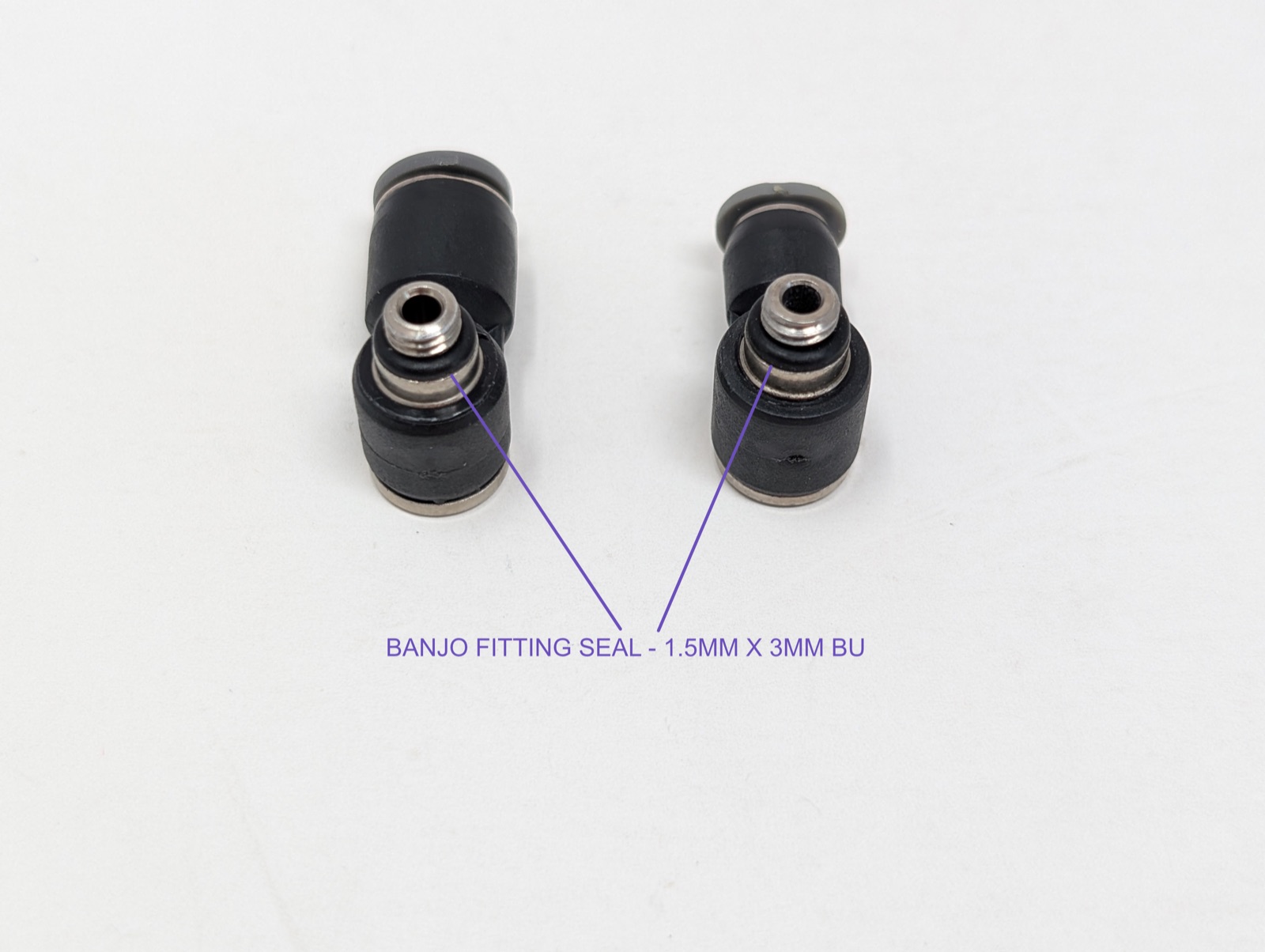
Both photos are mine — see the disclaimer for attribution terms.
Before you start: fully de-gas the marker, then separate the frame from the body the same way as Teardown — remove the barrel, open the grip and disconnect the battery, remove the grip frame screws, and work through the banjo fittings — to reach the solenoid.
- Grip the sides of the bracket between your thumb and index finger and pull it straight off the back of the solenoid — this is usually enough on its own, though it takes a bit of finger strength, and not everyone can get a grip firm enough to break it free. If that's the case, use a 3/32" hex key instead: gently pry the bracket off, positioning the tool between the bracket and the upper black section of the coil, never near the red-wired section, which can be damaged easily.
- Pull the solenoid head straight up, then tip the body over to remove the armature. It comes out easily, so don't lose it.
- Clean the inside of the solenoid body and the armature with a cotton swab dampened in 70% isopropyl alcohol — no lubricant.
- Reassemble: armature back in (bumper end first), head pushed back onto the body, bracket reinstalled with its bent section on the underside.
Removing microline hoses from barb fittings
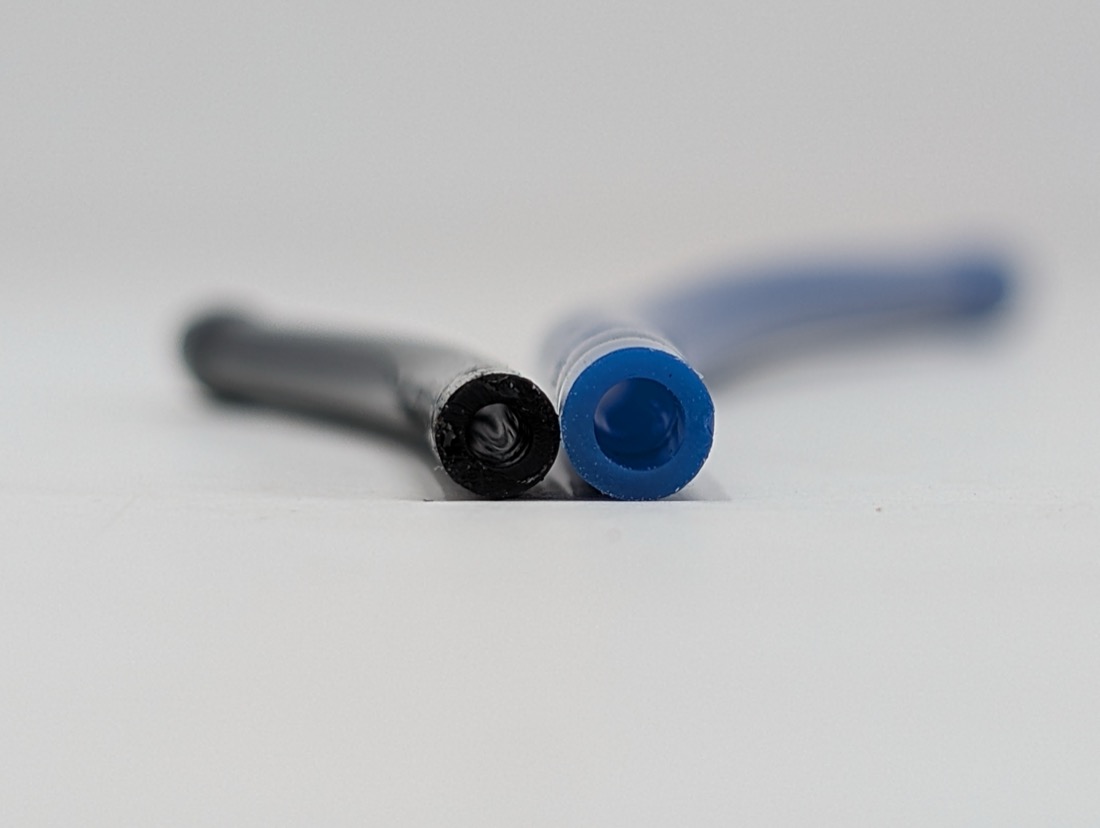
This is about pulling the flexible hose itself off a barb — for unscrewing a banjo fitting from the body, see Teardown. Cold microline grips a barb stubbornly. Warming it first — a hair dryer is the safer choice — softens the tubing enough to pull free by hand. A heat gun also works, but treat it carefully: even on its lowest setting, it heats up much faster and hotter than a hair dryer, and it's easy to overheat the hose or a nearby part before you notice. Slip-joint pliers are a reliable alternative to heat — grip with just enough force to twist the tubing free, not so much that you crimp it. Microline is fairly forgiving, especially when it's cold, so there's more margin here than it might feel like.
For the 5/32" microline, removing the solenoid head first (as above) gives much better access to the barb.
More than you want to tackle yourself? Check out the finished builds or get in touch to have your Ion serviced.