Ion 1.0 / Trigger & Grip Frame
Trigger & Grip Frame
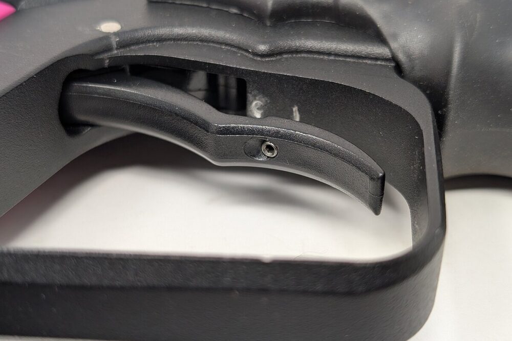
Two set screws control the Ion's trigger feel: post-travel (how far back the trigger swings) and the magnet screw, which controls pre-travel and pull tension together — it's a single screw that sets both, since it's positioning one magnet.
Post-travel screw
A small setscrew located inside the trigger blade itself, adjusted with a 3/64" hex key. Turning it in stops the trigger sooner after it fires the marker; turning it out lengthens the stroke, making the pull feel "sloppier." Once you've found a setting you like, a drop of purple/low-strength threadlocker (Loctite 222 or equivalent) keeps it from vibrating loose during play without making future adjustments any harder — skip the stronger blue or red grades here. Blue (Loctite 242) is rated for fasteners removed only occasionally, not readjusted by feel between rounds the way this screw is — every time you break and reform that bond it takes more torque to loosen than the last, and a setscrew this small strips its hex socket long before a medium-strength bond gives up. Red (Loctite 271) is a permanent bond that needs real heat, upwards of 450°F, just to break free at all — not something to apply next to a composite grip frame for a screw you're supposed to keep retuning.
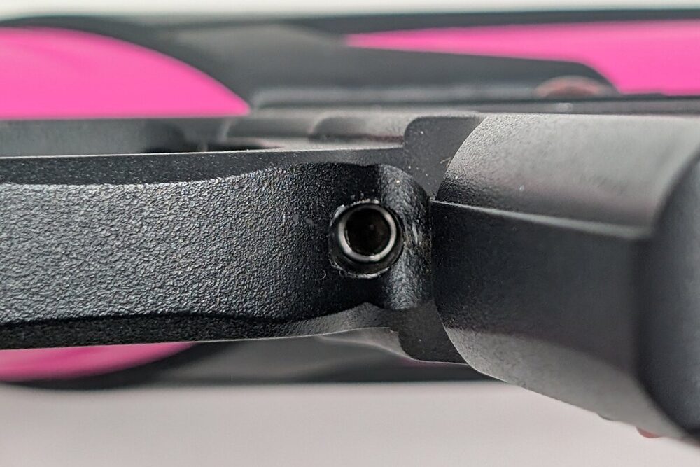
Magnet screw
Located at the base of the trigger guard, in front of the rubber grip within the grip frame, adjusted with a 1/8" hex key — this single screw sets both pre-travel and magnetic pull tension. Removing at least half of the grip is necessary to access it, since the front grip's curvature blocks the screw otherwise; this can vary with aftermarket grips of a different shape. Turning it in brings the trigger closer to the switch and increases pull weight, shortening the pull and making it feel "snappier"; turning it out lengthens the pull and lightens the pull weight. Same threadlocker approach as the post-travel screw once you've dialed it in — a drop of purple/ low-strength (Loctite 222) rather than blue or red.
If the trigger won't fire the marker
Check whether either set screw is turned in too far, putting constant pressure on the trigger switch — back both screws out gradually until the marker fires normally again. If that doesn't resolve it, the trigger switch itself may be damaged and need replacement — see Troubleshooting.
Removing or replacing the trigger
Needed either for cleaning out debris jammed between the trigger and frame, or to install an aftermarket trigger.
- Fully de-gas the marker — cycle it with the air source removed until it will not fire — before doing anything below; the front microline fitting you're about to disconnect can still be under pressure otherwise.
- Remove the grips and disconnect the battery.
- Separate the frame from the body, disconnecting the front microline fitting with a 1/8" hex key. Set the body aside gently.
- Punch out the trigger pin — the small pin located directly above the trigger in the frame — using a 3/32" punch (I use a Wheeler Hammer and Punch Set) or a snug-fitting nail and a hammer.
- The trigger slides up and out of the frame once the pin is out.
- Slide the new trigger in and reinstall the pin. Aftermarket triggers that use a screw instead of a roll pin (common on aluminum/polymer aftermarket options) follow their own included instructions instead of this pin-punch step.
- Readjust both set screws to taste — a trigger swap resets your stroke and tension feel from scratch.
Aftermarket triggers generally fall into two camps: standard roll-pin mount (same procedure as stock) or bearing-pivot triggers that mount with a screw instead — check which one you've got before assuming the pin-punch method applies.
Power button
The stock power button is a sticker sitting directly over the circuit board's power switch. Peeling it back isn't actually the best way to reach the switch for troubleshooting — for real access, pull the board and solenoid out of the grip frame instead (see Electronics). Peeling the sticker is mainly for cleaning behind it, or for swapping to a different button: the Epiphany-style plastic push-button (see On/Off Buttons), or an aftermarket sticker button — historically a Virtue product, and a longtime fan favorite. The stock sticker generally sticks back down fine after peeling; if it won't, a fresh dab of adhesive holds it.
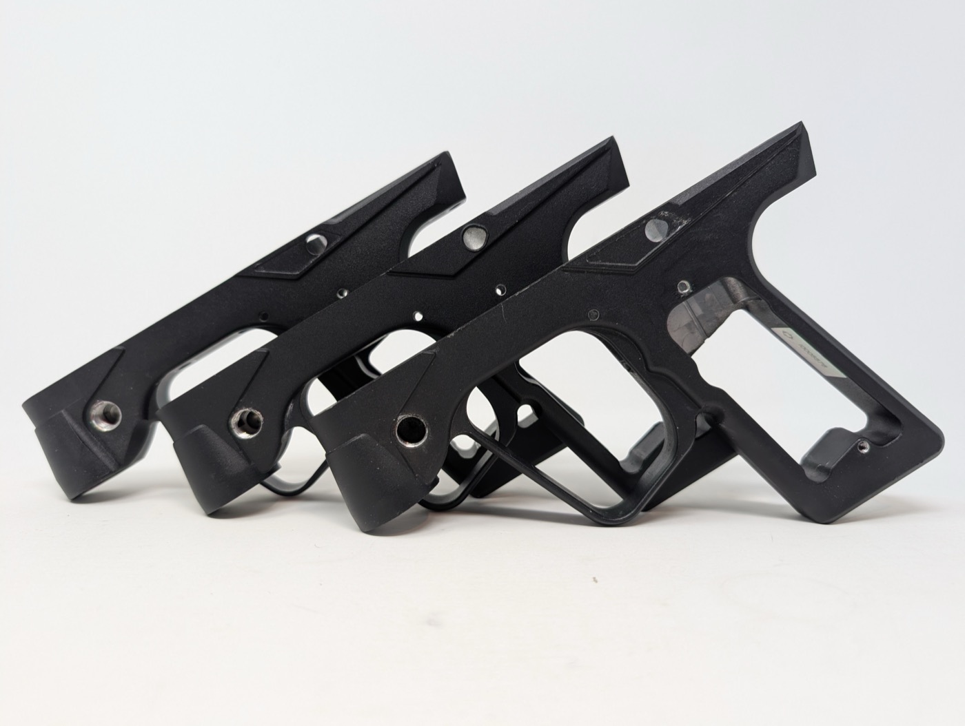
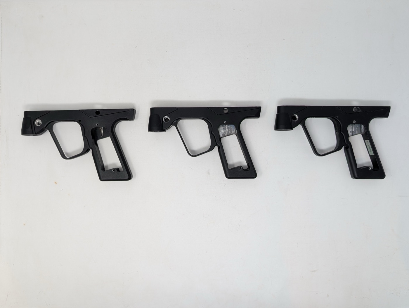
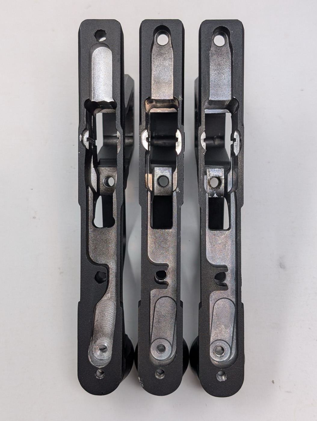
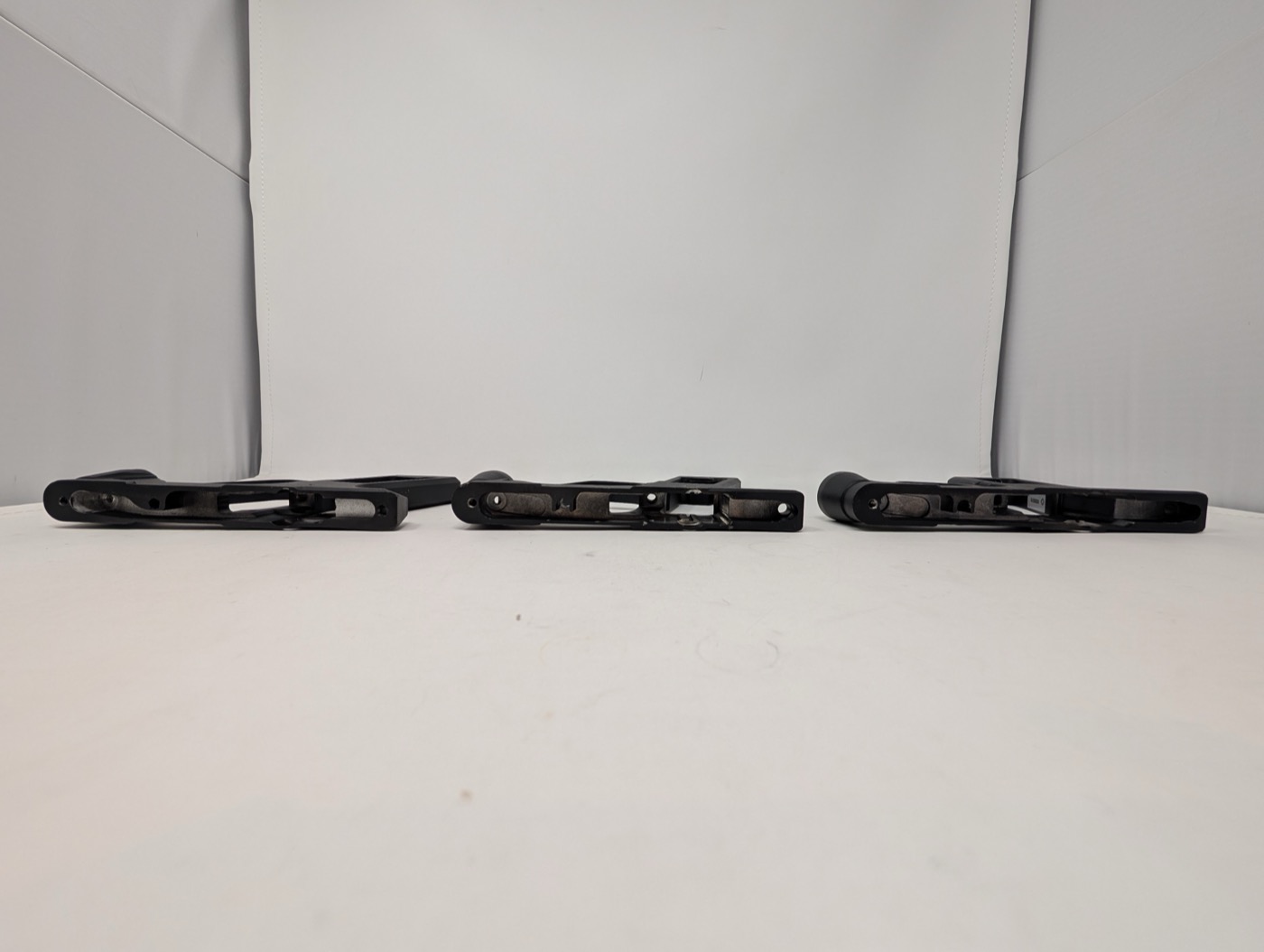
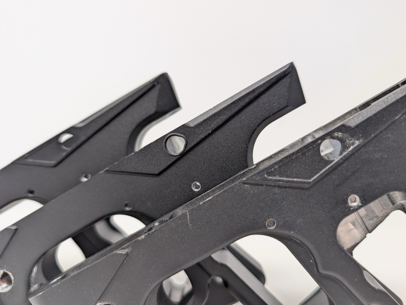
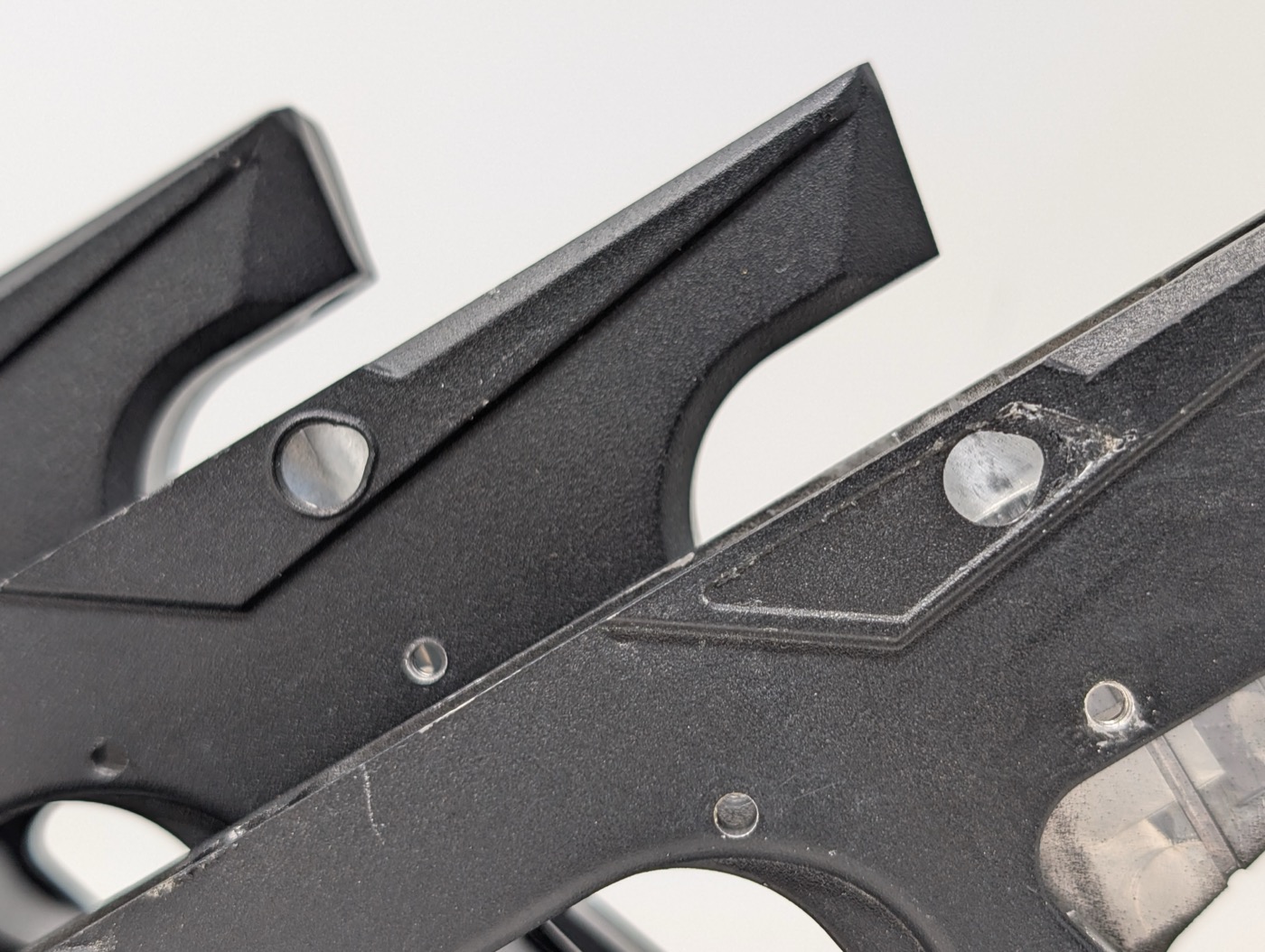
Grip frame across generations, side by side
Ion 1.0, Ion 2.0, and Ion XE grip frames, left to right in every photo below. The only real difference between them is the on/off button mounting described in the Power button section — overall shape, trigger guard, and the internal steel frame are the same across all three, and these photos are here to show that directly rather than just assert it.