Epiphany / Teardown
Teardown
The overall sequence closely follows the standard Ion, with a few Epiphany-specific parts and one important warning about grip screw length. For the fire chamber insert system specifically, see Volume Inserts — this page covers getting there.
Before you start: remove the hopper and all paintballs,
then fully de-gas the marker — cycle it with the air source removed
until it will not fire. Point the barrel in a safe direction with a
barrel blocker on throughout.
Video: Full Epiphany teardown, start to finishComing soon
What you'll need
- 5/64", 1/8", and 5/32" hex keys
Also worth having on hand: those three hex keys are
all that's required to get the marker apart. But the actual point of
a teardown is maintenance, not just disassembly — assessing the
marker's condition, cleaning wherever it's dirty, and regreasing
wherever grease looks like it needs it. For that, keep a microfiber
towel (or another lint-free cloth) and Molykote 33 Light (formerly
Dow Corning 33 / "Shocker Lube" / SL33K) within reach while you work.
Epiphany grip screws are shorter than an Ion's. Using
Ion-length screws on an Epiphany grip can damage the circuit board —
keep the sets separate if you're working on both.
Disassembly
- Remove the barrel, then remove the body flat cap screw normally concealed underneath it (1/8" hex key).
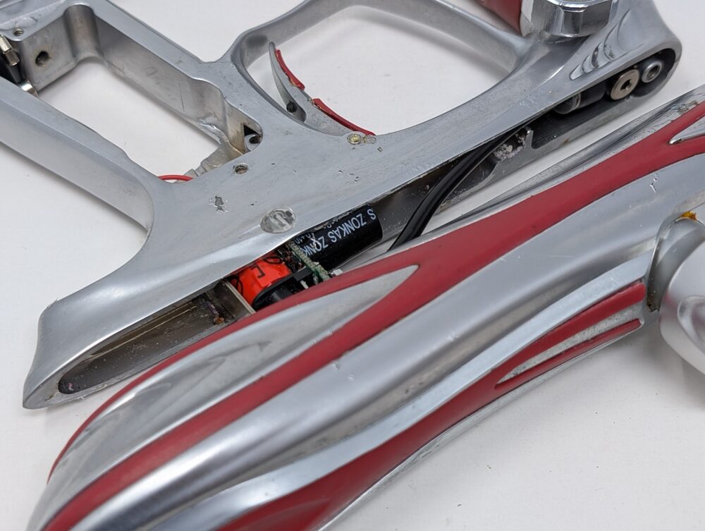
- Remove both left-side (gauge side) grip screws (5/64" hex key) and open the flexible grip. Unplug the battery clip by grasping the connector directly — never pull on the wires.
- Remove the right-side grip screws and the flexible grip — the upper right screw can catch on the circuit board, so take this slowly.
- Remove the front and rear grip frame screws (5/32" hex key).
- Grasp the body and grip frame separately and slowly pull the body away, rolling it slightly to the side to expose the top of the grip frame and the front banjo fitting. A thumb gently pressing up on the circuit board helps it slide free.
- Remove the front banjo fitting over the vertical adapter (1/8" hex key) — the center of the fitting pivots as you turn it.
- Finish separating body from grip frame, keeping the circuit board, battery wires, and battery clip from catching. Set the grip frame aside, body upside down.
- Locate the Vision wiring harness (four black wires) and unplug it from the body end, pulling on the connector itself, not the wires.
- Remove the remaining two banjo fittings (1/8" hex key).
- Slide the inner receiver components out of the body cover.
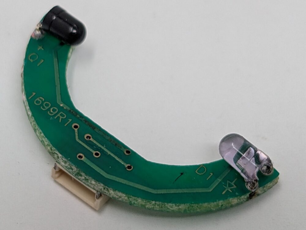
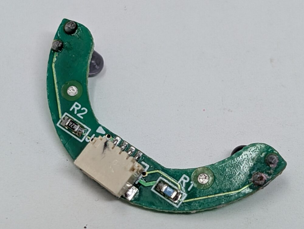
- Remove the Vision circuit board from the body breech — it's C-shaped and lifts out easily. Keep the emitter/detector (clear LED-like parts) away from anything that could scratch them.
- Unscrew the body breech from the fire chamber and remove the bolt. If the bolt stop doesn't come with it, pull it out separately.
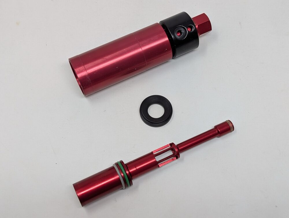
From here, see Firing Assembly for inspection and o-ring replacement on the Firebolt and bolt stop, Electronics — Solenoid service for removing the solenoid bracket and cleaning the internals, or Regulator & ASA for regulator service.
Reassembly notes
- Grease all bolt and bolt stop o-rings lightly with Molykote 33 Light — no other lubricant (see Firing Assembly for why grease, not oil, is right for this style of valve).
- Seat the bolt stop with its concave side — shaped like the inside of a cone, per the official manual — facing the rear of the marker and its flat side facing forward, and make sure the fire chamber insert is fully seated before screwing the fire chamber into the body breech. A backwards bolt stop is the classic cause of the grip-frame screw holes not lining up after reassembly.
- The Vision board's connector-side faces the rear; the clear emitter/detector faces the front of the body breech.
- Reassemble in reverse order, taking the same care with wires and banjo fittings as during disassembly.
More than you want to tackle yourself? Check out the finished builds or get in touch to have your Ion serviced.