Epiphany / Firing Assembly
Firing Assembly
Full Firebolt and firing assembly rebuild, picking up exactly where Teardown leaves off — this page doesn't repeat that disassembly, just what comes after it.
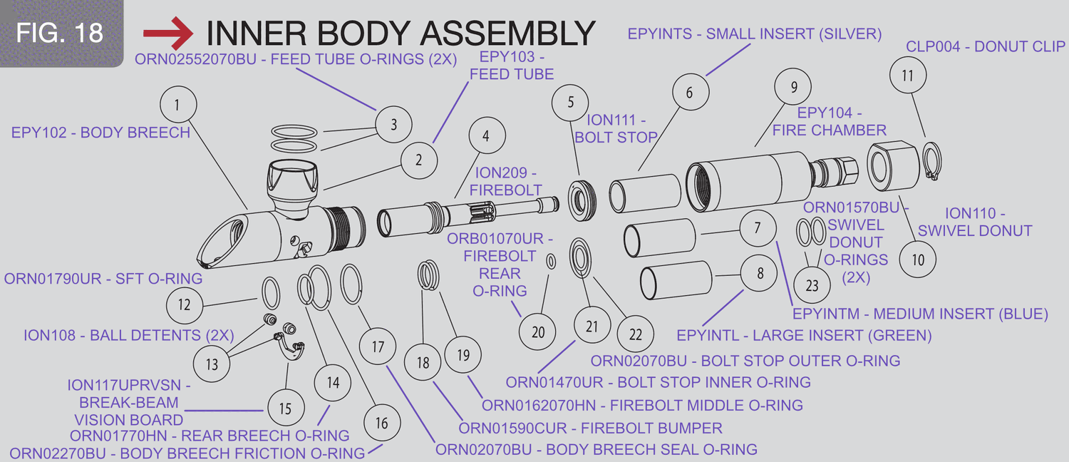
The Epiphany’s Firebolt isn’t just the moving part — it is the valve, the same way the standard Ion’s bolt is. As it slides forward to close the body breech, air transfer ports inside the bolt itself open and release pressurized air through it. There’s no separate valve assembly; the firing assembly (fire chamber, bolt, bolt stop, body breech, and swivel donut) does double duty as both the marker’s action and its valve.
Getting there
This picks up exactly where Teardown leaves off — same disassembly (grips open, body separated from the grip frame, Vision board out), same parts already sitting loose once you’re there. Nothing here is reachable with the marker still assembled.
What’s actually new on this page, that Teardown doesn’t cover: pulling every o-ring for inspection and replacement (Teardown’s own bolt/bolt-stop step is a visual check and reseat, not a full rebuild), plus the feedneck and the donut clip/swivel donut — two parts Full Teardown never touches at all.
What you’ll need
- 1/8” hex key (also works for pulling a ball detent to inspect or replace it)
- Full o-ring kit for the Epiphany (see O-Ring Specs for exact sizes)
- Molykote 33 Light (formerly Dow Corning 33 / “Shocker Lube” / SL33K) — see Firing Assembly for why grease, not oil, is right for this style of valve
- 70% isopropyl alcohol (an ultrasonic cleaner works well for a thorough pass), or an aircraft-safe electronics cleaner
- Two lint-free cloths — one to clean with, one to set parts on
- Snap-ring pliers, sized to fit (only if removing the swivel donut)
- A rubber strap wrench (only if removing the feedneck)
Service interval
Same as the standard Ion — ideally after every day of play. Staying on top of it keeps future disassembly easier, since grease that’s had time to gum up is what makes bolts seize on removal.
Removal
- Unthread the fire chamber from the body breech — it’s simply screwed on, no fasteners involved.
- If a volume insert is installed and you want it out, reach a finger into the fire chamber and pull it straight out — no tools needed. Otherwise leave it in place.
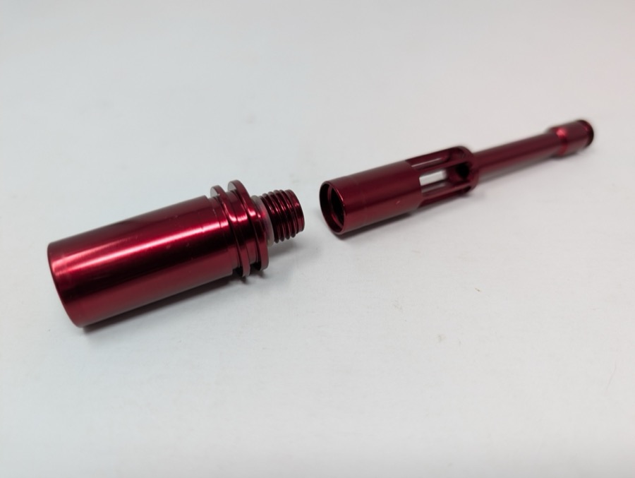
- Slide the bolt and bolt stop out together. If they resist, it’s almost always grease buildup, not corrosion — don’t force it.
- Separate the bolt from the bolt stop.
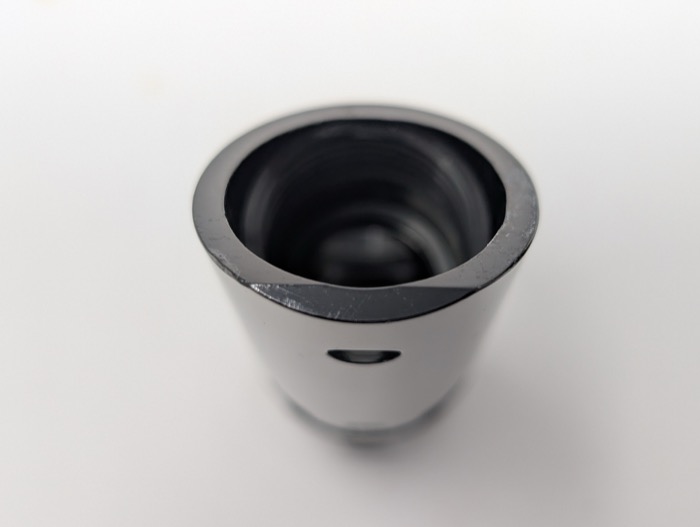
- The swivel donut, at the rear of the fire chamber, rarely needs removal for routine service — leave it attached unless you’re chasing a specific leak there. If you do need it out: compress and remove the donut clip (CLP004, retaining it) with a properly sized pair of snap-ring pliers, then slide the donut out. Two more o-rings (ORN01570BU) sit underneath it, exposed only once it’s off.
Inspection points
Check every o-ring you can see for flattening, swelling, or embedded debris. Exact sizes for each are on the O-Ring Specs page:
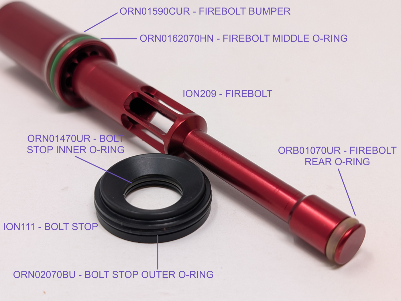
- The Firebolt rear o-ring, on the tail of the bolt, where it seals against the body breech
- The Firebolt bumper and middle o-rings, both on the bolt head — three o-rings total on the bolt itself
- Both bolt stop o-rings — two different sizes on the same part, not one
- The body breech seal, friction, and rear breech o-rings — three more o-rings in the breech itself
Ball detents
The body breech is the same part as the standard Ion’s, so it has the same two ball detents — each tip should extend roughly 1/16” into the body breech. If either falls short of that, replace it. Pry a worn detent out with a 1/8” L-shaped hex (Allen) key — the bend gives enough leverage to angle the short end under the detent and pop it straight out. Fingernails, needle-nose pliers, or an o-ring pick work too if that’s what’s on hand. If a detent is really embedded from paint packed in around it, work the long end of the hex key in from the backside of the detent — from inside the body breech — to loosen it first, then pop it out from within the breech. Press the replacement in with a thumb.
Reassembly and greasing
Grease all three o-rings on the bolt itself (bumper, middle, rear) plus both o-rings on the bolt stop, liberally enough to fully coat them, but not so much that it globs or squeezes out visibly once seated.
Seat the bolt stop into the body breech with its concave side facing the back of the marker and its flat side facing forward. Push it in evenly until it stops. Insert the bolt into the bolt stop/body breech. If you removed the volume insert, slide it back into the fire chamber before threading the fire chamber back onto the breech. If the bolt stop doesn’t seat flush, it’s almost always installed backwards or not pushed in evenly on one side.
Feedneck
The feedneck threads directly into the top of the body breech — same Ion/Shocker thread as the rest of the family. Removal goes easiest with the body already separated from the grip frame (see Teardown) — you’ll want something solid to grip while you work it loose.
Wrap a rubber strap wrench around the feedneck and turn it counter-clockwise, viewed from above. It can take real force to break free the first time — the rubber wrench provides that grip without marring the feedneck’s finish the way pliers or a pipe wrench would. Reinstall by threading it back in clockwise, hand-tight.
Related
- Fire Chamber Volume Inserts — tuning chamber volume and pressure
- Electronics — the solenoid sits directly below this assembly and should be serviced at the same interval
- Regulator & ASA — pressure setting and rebuild
- Troubleshooting

More than you want to tackle yourself? Check out the finished builds or get in touch to have your Ion serviced.